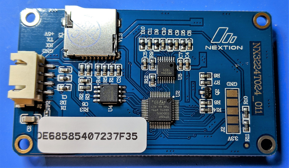
I’ve been buying a fair number of the Nextion 2.4 LCDs over the past couple years and I noticed that a new PCB version started shipping sometime mid-to-late 2018. It looked like a typical mid-life product refresh, a couple diodes added on the serial lines, some pieces moved around the board, nothing too drastic. One thing that seem a bit odd was the relocation of the serial number sticker.
Previously, the serial number sticker was placed on an empty section of the board, which seems like an obvious thing to do. However, on the new PCBs the sticker was relocated over a populated section of the board with parts underneath. This is weird because it doesn’t stick too well to an irregular surface and there is still plenty of room on the board elsewhere with no parts placed where it would stick just fine.
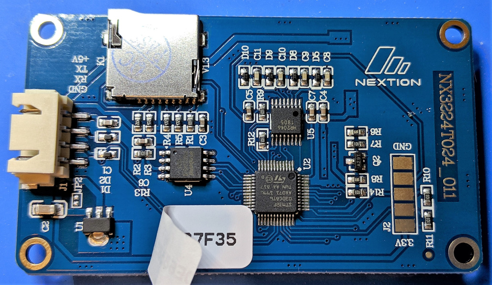
I didn’t spend much time stewing on this right up until the fateful day that I did something pretty stupid - working in haste I reversed the +5V and GND pins on a board I was assembling, plugged it in for unit testing, and … nothing happened. Well nothing I noticed right away anyway… until I looked at that serial number sticker!

Let’s peel that back and take a look underneath…
With the sticker out of the way we can now see the lump - it’s a 3pin SOT89-3 package IC labeled U1. Let’s take a closer look:
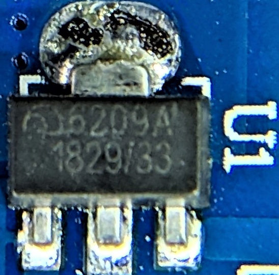
This appears to be a Nanjing Micro One 6209 series 3.3v LDO voltage regulator, taking the +5VDC supplied to the board and dropping it to the 3.3V most of the components on the board require.
Voltage regulators don’t much like it when you apply reverse voltages to them and this one is no different. The serial number sticker is a thermal label, so when I screwed up the voltage it immediately started heating up the regulator, and the result was visible on the sticker. After a few choice expletives, I pulled U1 off of a doner board, swapped out the part, and everything worked as I would expect (this time with the voltage applied correctly!).
So here’s the thing - effective reverse voltage protection can be as simple as a single diode, a part which costs less than a penny to place on your board. That diode will involve a voltage drop, but that’s no problem at all when you’re running straight into a regulator that’s going to drop more voltage anyway. It’s cheap, and it’s A Good Idea for any design where end-users are manually connecting power to your device.
But… you know what’s even cheaper? Moving the serial number sticker over the part that will smoke when the user applies the wrong voltage. You now have clear and immediate cause to deny a warranty claim, with no reason to add less than a penny to your BOM. Now that’s smart thinkin’!
If you find yourself in this predicament, and you don’t have the luxury of flying with these things in your suitcase so TSA picks them out, drops them on the floor in front of you shattering the screen and then asking “what’s this” (and who should have been asking “what was this before I FUCKING SMASHED IT ON THE GROUND”), thus leaving you with a board full of parts to scavenge, then you can check here for a suitable replacement.


