Issue solved. It was a power issue, not a firmware issue.
Setup
My device (microcontroller plus Nextion) is powered by my notebooks USB3 port. I don’t know if it’s capable of 1A, 1.5A or more but it is the “charging” port for charging phones, etc and certainly fulfills the minimum requirement of 500mA. I’m using a thick, good quality USB cable. I haven’t cut it open but it’s certainly not a thin cheapo one.
Observations
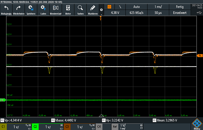
Although this setup should be good enough, it’s not. Measuring the 3.3V and 5V rail on the Nextion PCB itself I can see a high ripple caused by the background LED PWM. The lower peak on the 5V rail goes as low as 3.7V, which the 3.3V reg can’t compensate anymore, making the 3.3V line sag to 2.6V for a short time.
These results are visible on the attached scope image, C1 (yellow) measures the 3.3V rail, C3 the 5V rail. The white traces are explained below.
When increasing the backlight intensity to 100% everything is okay, and indeed, the application immediately runs faster again. Very weird how you can switch between fast and slow while it’s running. At 100% backlight the 5V line sits at 4.5V which is well in spec (USB hardware - Wikipedia ).
Interpretation and solution
The 100% backlight test proves that my USB port, the cable, the connections, … is well capable of handling the full LED current. However, the transient response is bad - likely caused by cable inductance. This cannot really be solved by a better cable, since inductance isn’t much dependent on the wire diameter. With 1m the cable isn’t exceptionally long, but rather a pretty common size.
As every PCB designer probably knows, the solution is local decoupling. Therefore I soldered a 220uF 63V low-ESR capacitor to the connector on the Nextion screen itself. Sure enough the voltage rating is way too high but I didn’t have anything else at hand.
Result: The excessive dips are gone. Except for noise the 5V rail stays above 4.45V which makes it USB compliant. The 3.3V line is perfectly stable. All issues are gone no matter the Nextion firmware version.
These observations are again visible in the scope screenshot. R1 and R3 show the 3.3 and 5V rail.
Further thoughts
I’m not the first one who added a decoupling capacitor. Apparently it also helps a lot with reducing noise that the Nextion screen injects into the rest of the system - which totally makes sense to me after seeing these scope shots. Possibly much less than 220uF would already be sufficient. This is not a big BOM item but it would certainly make the screen more reliable - which for industrial clients is probably well worth the extra 0.2$ costs.
I also measured the 3.3V rail on my microcontroller board (Tiva TM4C1294XL) and it doesn’t experience any sagging. Apparently they do use a proper LDO regultator. Price difference between LDO and standard 3.3V reg shouldn’t be significant, making this a low hanging fruit for more robustness.
Finally, I still wonder what v1.62.1 has to do with all this. Why did it suddenly start to become picky about that voltage dip or why wasn’t any previous version sensitive to this. I don’t know. Also, I’d have expected crashes and similar things, but not that its execution speed drops by 50%. Did v1.62.1 potentially include some kind of power management? If a brown out is detected, reduce CPU clock? That would be fancy, but rather unlikely I think.
Anyways, I don’t think v1.62.1 is the one to blame here. Handling voltage drops like this isn’t the job of a firmware IMO.
Kind regards,
Max
