If you are sure there is a valid PWM signal, it’s something with your driver board.
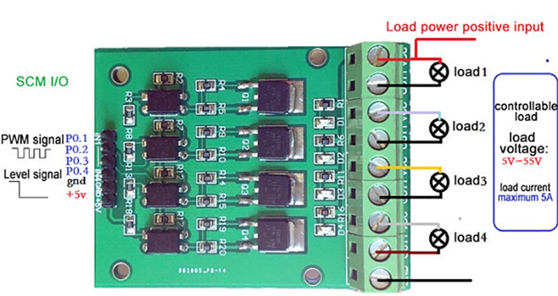
It’s designed for DC 5V>24V the Nextion output is minimal 3,0V and max 3,2V !
That could be the problem in your case.
When there isn’t a good signal, in default the driver board will continue stay active.
(20% duty, is 80% output !)
The nominal output current of the Nextion GPIO is 1mA - most times not enough to drive an optocoupler. Since, on top of that, the logic voltage is 3.3V (the 5V standard is outdated in industrial designs), you‘ll need a combined buffer and level converter like TI‘s SN74LV4T125 to drive your board.
thank you guys, was apparently a classical think-before-solder fail: the small Nextion IO Adapter which comes with the needed cable and gives you the 8 GPIO pins plus 5V. But 5V supply does not mean 5V signal, right?
So not even having 3.3V supply for a level shifter, I went for the IRF5020 mosfet breakout boards (no optocouplers), one for each channel
This forum is in no way affiliated with NEXTION®, ITEAD STUDIO®, TJC®, or anyone else really. All product names, logos, and brands are property of their respective owners. All company, product, and service names used in this website are for identification purposes only. Use of these names, logos, and brands does not imply endorsement from the respective rights holder(s).